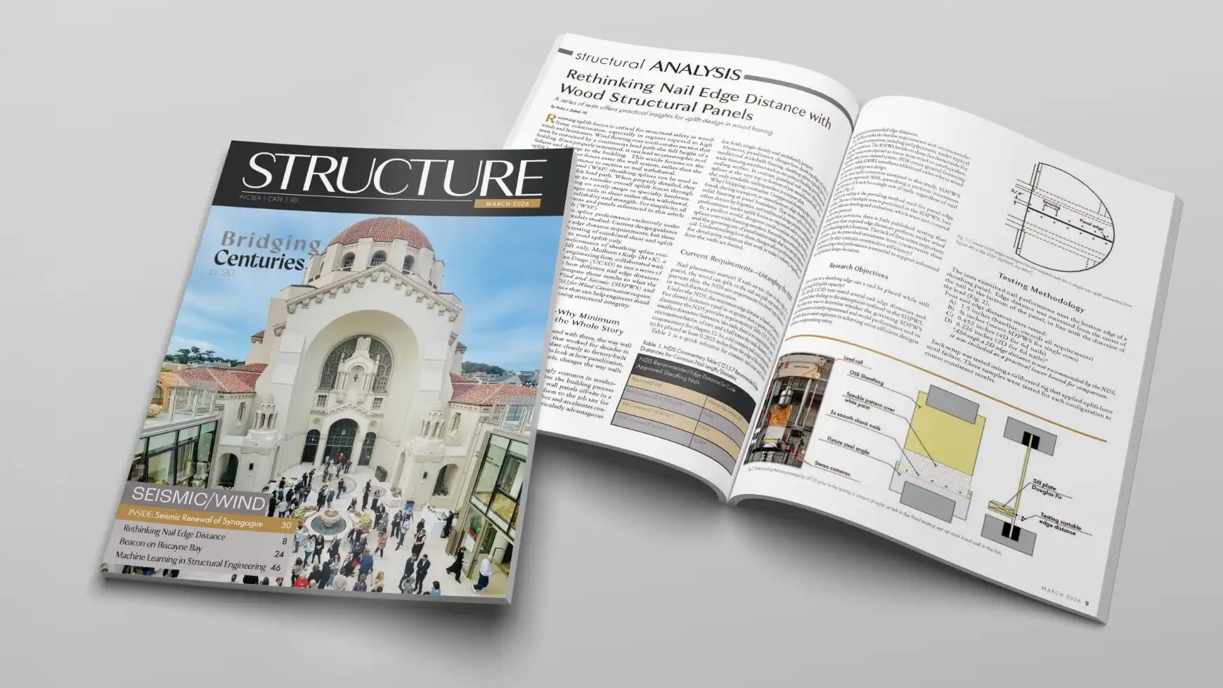
Research from M+K, developed in partnership with the University of California, San Diego, has been published in the March issue of Structure Magazine. The article, “Rethinking Nail Edge Distance with Wood Structural Panels,” by Ricky Zabel, P.E., Director of Engineering highlights findings that could influence how engineers approach nail edge distance, specifically in splice designs carrying wind uplift.
M+K’s Research with UCSD Published in Prestigious Journal
Our collaborative research with the University of California, San Diego has just been published in the Journal of Building Engineering!
So why does this matter? Simply, our study helps bring clarity to an engineering “gray area” that affects modern wood construction. Specifically, we tested how close nails can be placed to the edge of wood panels while still achieving their full strength in resisting wind uplift. For years, code requirements around this issue have been conservative, inconsistent, and—most importantly—lacking real test data.
What we discovered:
- The industry’s current rules weren’t based on actual testing.
- Our data shows that nail spacing can be more efficient than codes currently require—without sacrificing safety.
- This research helps align construction standards with how buildings are really being designed and built today, especially with the growth of panelized construction.
In short, it’s a step toward smarter codes, more efficient design, and safer structures.
A huge thank you to our partners at UCSD and our own M+K team who pushed this forward. This is the kind of work that helps shape the future of building science.
You can read the full article now in the Journal of Building Engineering here.
Scaling Faster and Staying Ahead of the Curve: COO Jamie Friling on the Future of Structural Engineering
From his journey as a structural engineer to the technology transforming the field, Jamie shares insights on how firms can leverage digital solutions to work smarter, scale faster, and stay ahead of the curve.
M+K Published in JLC Magazine

Drawing from his two decades of residential engineering experience, M+K project manager Jason Bischoff, P.E., writes in the July/August 2024 issue of Journal of Light Construction about the pitfalls of leaving construction errors unchecked—illustrating how even minor errors can lead to costly and complex retrofits if not addressed promptly.
Avoiding Costly Structural Repairs
In my role as a project manager for a national structural engineering firm that specializes in residential design, I have the opportunity to learn about thousands of construction errors on a regular basis. Our firm has more than 65 engineers on staff working on projects across the U.S., and we are regularly tasked with providing quick turnaround retrofits to resolve construction errors to keep projects moving forward. From this well of experience, we’ve compiled a short list of the common construction errors with the most impactful retrofit requirements, along with some recommended preventative measures. Most of the situations described here can be avoided with oversight and awareness but are likely to balloon into major problems when overlooked. In most cases, the longer a construction error goes unaddressed, the more expensive it becomes to correct.
Out-of-Square Footings and Foundations
The need to keep footings and foundations square should be obvious, right? Still, nothing will stop a job quicker than finding out the foundation wall forms are overhanging the edge of the footing or the sill plates are overhanging the foundation walls. When these problems occur, it is worth pausing and reaching out to a design professional for direction on how to compensate. In some cases, the solution may be as simple as fastening a ledger to the side of the foundation to provide support for an overhanging sill plate. But in more drastic instances, more extensive or creative modifications to the foundations may be required. Depending on the scenario, it could be a much more difficult repair after the walls have been poured and even worse once the framing is installed.

Prevention: Measure twice, pour once. Make sure all measurements are checked prior to pouring. We recommend having an established process that clarifies whether the builder or the foundation contractor is accountable for verifying all dimensions prior to pouring the walls and footings and before any framing is set. Preferably, this is defined in writing in the subcontractor agreement.
Out-of-Level Foundations
A foundation that’s not level shouldn’t be much of an problem if it’s caught early. In an ideal situation, the framers install their sill plates as level as possible, shimming where necessary and checking level as subsequent levels are framed. It is imperative to check for level across all bearing points of a foundation. For example, if exterior wood-framed walls are bearing on a perimeter stem wall determined to be level, but the interior bearing walls are supported on a slab that is too high or too low, that is a recipe for major retrofits to those framed walls if not addressed early.
Prevention: Builders and their subcontractors need to ensure they are building from a level baseline, across all bearing points of the structure. A datum point should be established at one of the structural bearing points, and a laser or builder’s level should be used to verify that the rest of the structural bearing points are at the same elevation as the datum point. Continue reading “M+K Published in JLC Magazine”
M+K Announces Higharc Strategic Partnership
All of us at M+K are thrilled to be part of Higharc’s latest investment round to fund continued development of their innovative cloud platform for homebuilding operations that delivers much needed integration and automation, from plan concept to purchasing to sales, using generative AI based workflows.
Innovation and process improvement are integral to our DNA. With that in mind, we’re quite excited about how this partnership promises to support M+K’s vision to streamline plan development and management.
Like all our valued relationships and strategic partnerships, we’re looking forward to the opportunity to offer insight and perspective to the Higharc team.
Want more info? Check out the article in Forbes and Higharc’s press release below:
Forbes Article
Higharc’s Press Release
M+K Article Published in STRUCTURE Magazine

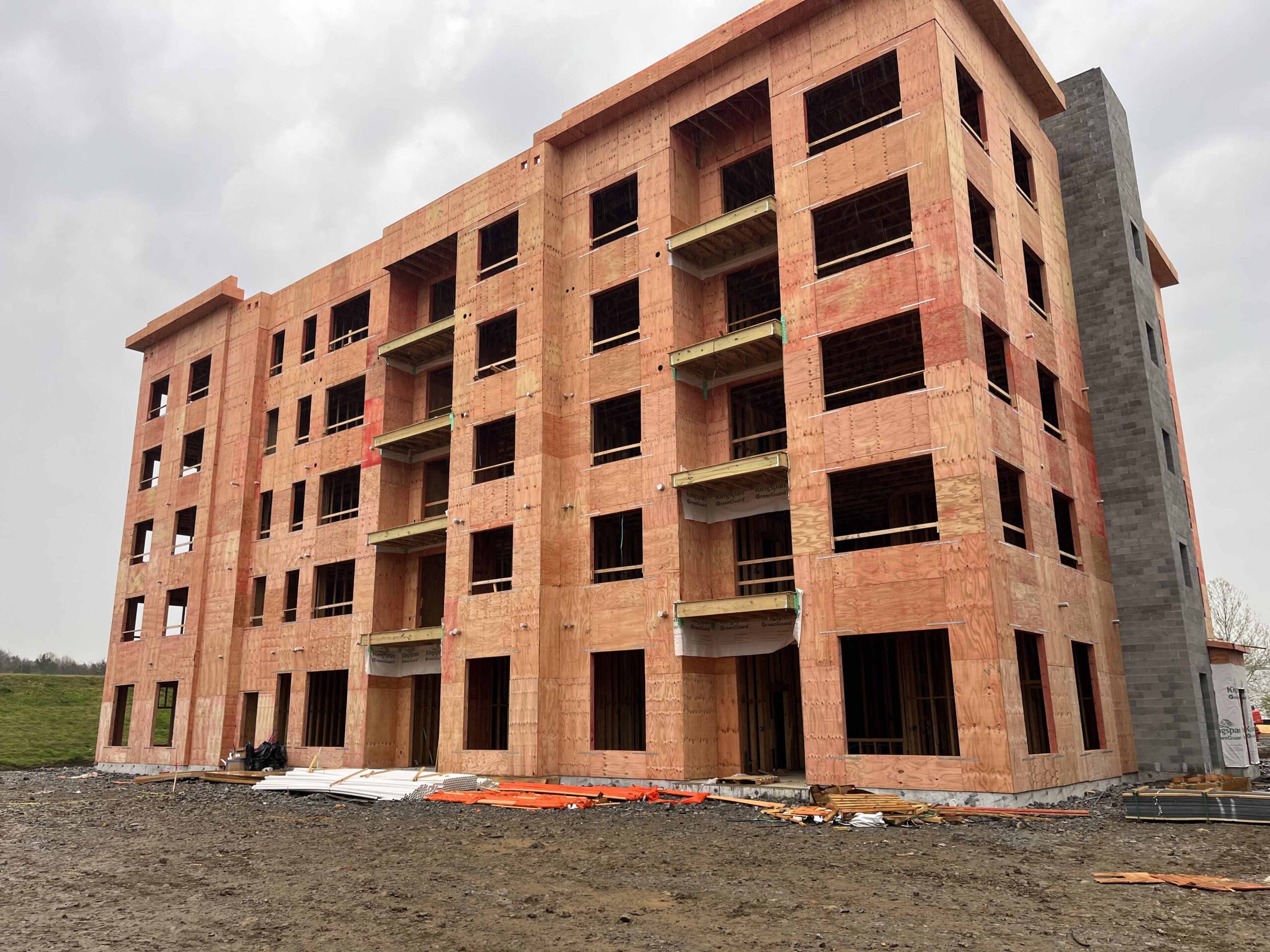
Our article in Structure Magazine outlines our holistic approach to designing 5-story wood-framed buildings utilizing Type III construction. Congrats to co-authors Jared Hudson, P.E., and Shaun Kreidel, S.E. Great job!
A Practicing Engineer’s Approach to Wood-Framed Type III Construction
Design considerations and common detailing strategies for Wood-Framed Type III construction are discussed.
Light frame wood construction is often a desired construction method for low-rise multifamily structures due to readily available labor and materials, speed of construction, sustainability, and relatively low construction costs. A Type V construction classification as defined by the International Building Code (IBC) is commonplace for these structures; however, this construction type is limited to four stories of stacking wood construction. A Type III construction classification allows conventional wood-framed structures to include an additional level, bringing the allowable height to five stories above grade; see Figure 1 for an example of this type of construction. This construction type may be attractive to developers looking to maximize the occupiable square footage of a defined footprint while taking advantage of the many benefits that come with light-frame wood construction. To facilitate a Type III classification, unique structural and architectural detailing is needed to maintain the strength, stability, and serviceability of the wood-framed structure, as well as to address the applicable fire design requirements. These details are multidisciplinary in nature and require a high level of collaboration between the structural engineer, architect, and builder/developer to ensure that the project meets the owner’s expectations and the building code requirements of the Authority Having Jurisdiction (AHJ).
Depending on the requirements of a given project, practicing engineers may need to investigate certain design aspects that become critical when meeting the requirements of Type III construction. These design considerations include material requirements, fire-resistance rating requirements, the importance of designing for wood shrinkage, and structural detailing strategies to accommodate fire-resistance ratings at the intersection of the floor/roof assemblies and exterior wall assemblies.
Material Requirements
While construction Types I, II and III all require the use of non-combustible materials at exterior walls, the IBC recognizes the use of fire-retardant-treated (FRT) sawn lumber and FRT wood structural panel (WSP) sheathing as acceptable materials to satisfy the requirement under Type III construction. Practicing engineers should account for FRT lumber and FRT sheathing strength reduction factors due to the treatment process. The strength reduction factors are manufacturer-specific, thus coordination with the architect and builder/developer is recommended if the intended product is unknown.
FRT treatment process results in sheathing strength reduction factors which can decrease both the allowable spans and the lateral strength/stiffness of diaphragms or shear walls. FRT lumber treatment process also affects the structural properties of sawn lumber; the designer may need to augment the wall/header designs to mitigate these effects. Table 1 illustrates the strength reduction factors from two manufacturers of FRT sawn lumber. Assumed in-service temperature of the lumber is an important consideration that may cause variation in structural property values between manufacturers. High in-service temperatures of more than 100 degrees Fahrenheit will correspond to a greater reduction in strength and stiffness when coupled with fire retardant treatment. The engineer should also account for any wood incising reduction factors that might be needed to treat the lumber and consider using lumber that does not require incising to mitigate the amount of strength reduction. All minimum assumed FRT properties should be listed as design assumptions in the contract drawings to ensure that suitable lumber and WSP products are utilized.

A designer may encounter situations where spans or loads require structural properties beyond what FRT lumber alone can provide. At this time, there are no fire-treated engineered wood products on the market (e.g., LVL, PSL, LSL) known to the author. One strategy available to designers is to utilize a flitch beam; a composite beam that consists of FRT wood laminations bolted to a continuous steel plate. The FRT laminations of the composite assembly will maintain the non-combustibility requirement; however, special attention to detailing to adequately conceal the heads of the bolts of the flitch beam assembly will be required. The designer should also consider the expansion of the longitudinal steel due to elevated service temperatures for longer-spanning flitch beams. Another strategy that the designer can employ is the use of rolled steel framing members within the exterior wall. These members may require additional fire protection in addition to meeting the noncombustible requirements of the code; the project architect should be consulted for additional fire protection requirements of these members.
Fire Rating Requirements
Type III construction requires that exterior loadbearing walls satisfy a 2-hour fire-resistance rating (FRR). If exterior walls can be classified as non-load bearing, the FRR can be reduced to 1-hour for certain occupancies. A 2-hour FRR is usually accomplished by having two interior layers of gypsum board. Over the full perimeter of the structure, the added cost of an additional layer of gypsum board can be substantial. A common industry interpretation of a non-load bearing exterior wall is one that does not support anything but its self-weight and the self-weight of the walls above. The structural designer can strategically run the framing parallel or introduce girder members parallel with the exterior wall to avoid a load bearing situation. In doing so, a FRR of 1 hour can be utilized and thus an extra layer of interior gypsum board can be avoided. This approach and interpretation should be discussed with the project architect and the AHJ during design to ensure compliance with the local building code.
The vertical continuity requirements of the rated exterior wall assembly have been a hotly debated topic between jurisdictions and design professionals, but the requirements have finally been clarified in the 2024 IBC. According to Section 705.6 of the 2024 IBC, the exterior wall FRR shall extend continuously from the top of the foundation/floor system below to the underside of the roof/floor sheathing above. However, if the fire separation distance (as defined in the IBC) is greater than 10 feet, the exterior wall FRR is permitted to terminate at the underside of a ceiling (floor or roof) assembly having an equal or greater FRR than the exterior wall. Detailing at the floor levels and the roof level will need to conform to these requirements. Some commonly used detailing strategies that meet these criteria are presented later in this article. Continue reading “M+K Article Published in STRUCTURE Magazine”
M+K Article Published in STRUCTURE Magazine
Our article in this month’s issue of Structure Magazine examines how different lateral restraint system classifications can impact the bottom line. Kudos to the author – M+K employee Timothy R. Donahue, P.E.. Great job Tim!
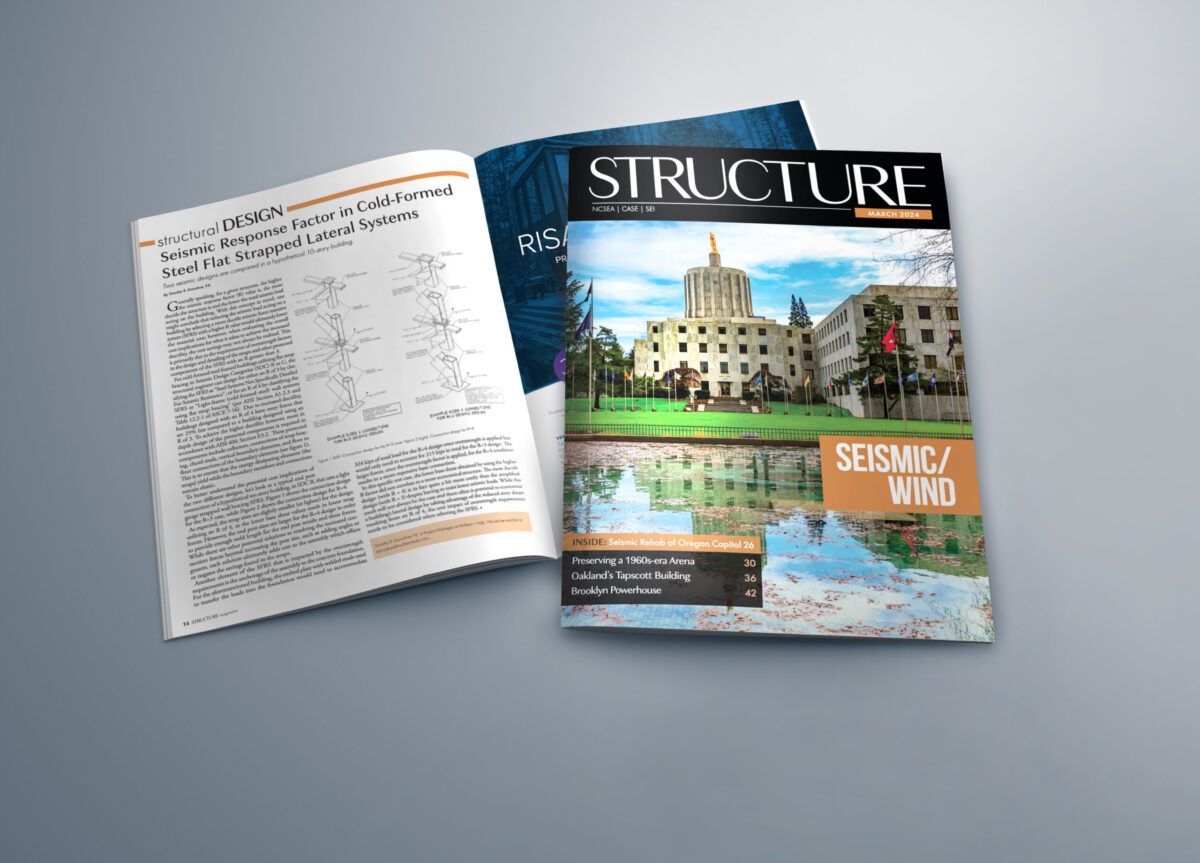
Seismic Response Factor in Cold-Formed Steel Flat Strapped Lateral Systems
Two seismic designs are compared in a hypothetical 10-story building.
Generally speaking, for a given structure, the higher the seismic response factor (R) value is, the more ductile the structure is and the lower the total seismic load acting on the building. With this concept in mind, one might conclude that reducing the seismic load acting on a building by selecting a more ductile seismic force restraint system (SFRS) with a higher R value would ultimately lower the material cost; however, when evaluating the overall cost implications for what it takes to achieve the increased ductility, the cost savings may not always be realized. This is primarily due to the requirements of overstrength factors in the design and detailing of the straps and other protected components of the SFRS with an R greater than 3.
For cold-formed steel framed buildings utilizing flat strap bracing in Seismic Design Categories (SDC) B or C, the structural engineer can design for either an R of 3 by classifying the SFRS as “Steel Systems Not Specifically Detailed For Seismic Resistance”, or for an R of 4 by classifying the SFRS as “Light-frame (cold-formed steel) wall systems using flat strap bracing” (per AISI Section A1.2.3 and Table 12.2-1 of ASCE 7-16).
Due to increased ductility, buildings designed with an R of 4 have story forces that are 25% less compared to a building designed using an R of 3. To achieve the higher ductility however, more in depth design of the protected components is required in accordance with AISI-400, Section E3.2. These protected components include collectors, connections of strap bracing, chord studs, vertical boundary elements, and floor to floor connections of the boundary elements (see figure 1). This is to ensure that the energy dissipating elements (the straps) yield while the boundary members and connections remain elastic.

To better understand the potential cost implications of the two different designs, let’s look at a typical end post connection of a hypothetical ten story building, in SDC B, that uses a light gauge strapped wall bracing SFRS. Figure 1 shows the connection design for the R=3 case, while Figure 2 shows the connection design for R=4.
As expected, the strap sizes are slightly smaller (or lighter) for the design utilizing an R of 4, as the lower base shear values result in lower strap forces. However, the end post sizes are larger for the R=4 design in order to provide enough weld length for the end post tensile and shear forces. While there are other potential solutions to resolving the increased connection forces beyond increasing the post size, such as adding angles or gussets, each solution ultimately adds cost to the assembly which offsets or negates the savings found in the straps.
Another element of the SFRS that is impacted by the overstrength requirements is the anchorage of the assembly to the concrete foundation. For the aforementioned building, the embed plate with welded studs used to transfer the loads into the foundation would need to accommodate 324 kips of total load for the R=4 design once overstrength is applied but would only need to account for 215 kips in total for the R=3 design. The larger forces, once the overstrength factor is applied, for the R=4 condition results in a more expensive base connection.
In this specific test case, the lower base shear obtained by using the higher R factor did not correlate to a more economical structure. The more ductile design (with R = 4) is in fact quite a bit more costly than the simplified design (with R = 3) despite having to resist lower seismic loads. While this result will not always be the case and there often is potential to economize a building’s lateral design by taking advantage of the reduced story shears resulting from an R of 4, the cost impact of overstrength requirements needs to be considered when selecting the SFRS.■
M+K Article Published in Structure Magazine

We’re very excited to have had the following article published in the November issue of Structure magazine. It goes without saying that we’re super proud of the M+K staff members who co-authored this piece: Bert Coelho, P.E. [Principal + Dir. Business Development], Kevin Quan, P.E. [Sr. Project Engineer], and Micah Milner, P.E. [Project Engineer].
Steel Stud Bearing Walls
An Alternative to Traditional Podium Levels
Developers are always looking for new and innovative ways to make buildings more profitable and financially efficient. Traditionally, a multi-story bearing wall building over one to two levels of steel or concrete, also known as a podium structure, has filled this need by offering high-density residential units at the upper levels and parking or retail spaces at the lowest floors. For multi-story residential buildings, wood construction is generally considered the most cost-efficient form of construction, followed by cold-formed steel (CFS) bearing walls and then heavy steel or concrete framing. Because of this, developers have sought to maximize the number of wood-framed floors over the podium level before switching to more costly materials.

Wood bearing wall systems are limited to either 4-stories using Type V-A construction or 5-stories using Type III-A construction. Both types of construction can be supported on grade or a podium structure. Podium structures have been covered extensively in previous articles by STRUCTURE magazine. They are proven methods of meeting not only financial requirements but zoning and regulatory obligations as well. This article focuses on an alternate hybrid system that maximizes the number of stacking levels of residential units by introducing multiple levels of CFS bearing walls to support the wood-framed levels before transitioning to the transfer level or foundation.
The Challenge
Recently, some developers have opted to add additional residential units below the Type V-A and III-A constructed units. This means the stacking residential units from above are carried down below the podium level by minimizing or removing the retail and parking areas altogether. This change increases unit density, thus maximizing more profitable areas by limiting the less profitable retail and parking areas.
The challenge with incorporating stacking units from above with a typical steel or concrete podium superstructure is the interference of regularly spaced columns with residential unit layouts. While the podium column scheme lends itself well to open spaces required for retail and parking, the standard grid pattern presents architectural challenges at residential levels in accommodating columns within the unit layouts. Additionally, non-stacking loads from the residential bearing wall system above inevitably require deep steel or concrete beams or heavily reinforced concrete slabs and may even require drop panels. The ideal column grid may also disrupt stacked window layouts along the exterior of the building below the podium level.
Architecture is not the only discipline to face challenges with this system. Plumbing, electrical, and HVAC systems are typically accommodated by having stacking mechanical penetrations for the full height of the building. In a wood-framed building, these are commonly located within the wall stud cavity. Therefore, stacked penetrations running down through the steel or concrete podium structure invariably conflict with beam and column locations that directly support the walls above.
To resolve these issues, architects frequently need to create new unit types and floor layouts to work around the traditional podium structural elements. Unfortunately, the new layouts can create spaces that may be inefficient or undesirable to developers or prospective tenants. Continue reading “M+K Article Published in Structure Magazine”