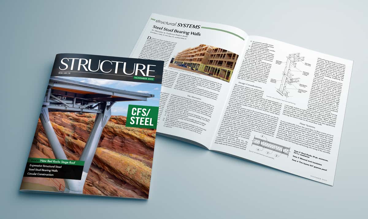
We’re very excited to have had the following article published in the November issue of Structure magazine. It goes without saying that we’re super proud of the M+K staff members who co-authored this piece: Bert Coelho, P.E. [Principal + Dir. Business Development], Kevin Quan, P.E. [Sr. Project Engineer], and Micah Milner, P.E. [Project Engineer].
Steel Stud Bearing Walls
An Alternative to Traditional Podium Levels
Developers are always looking for new and innovative ways to make buildings more profitable and financially efficient. Traditionally, a multi-story bearing wall building over one to two levels of steel or concrete, also known as a podium structure, has filled this need by offering high-density residential units at the upper levels and parking or retail spaces at the lowest floors. For multi-story residential buildings, wood construction is generally considered the most cost-efficient form of construction, followed by cold-formed steel (CFS) bearing walls and then heavy steel or concrete framing. Because of this, developers have sought to maximize the number of wood-framed floors over the podium level before switching to more costly materials.
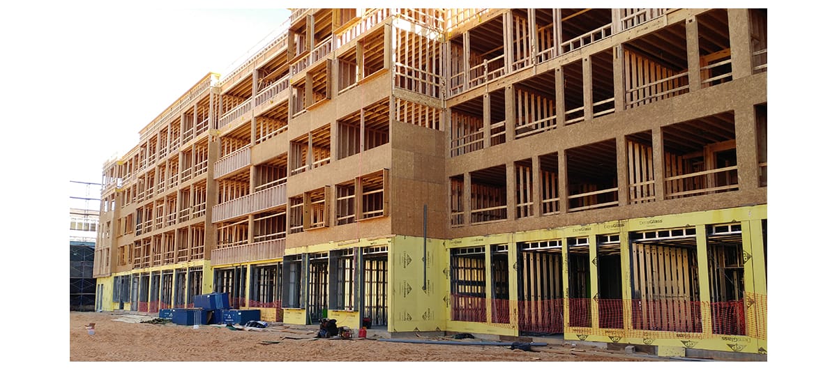
Wood bearing wall systems are limited to either 4-stories using Type V-A construction or 5-stories using Type III-A construction. Both types of construction can be supported on grade or a podium structure. Podium structures have been covered extensively in previous articles by STRUCTURE magazine. They are proven methods of meeting not only financial requirements but zoning and regulatory obligations as well. This article focuses on an alternate hybrid system that maximizes the number of stacking levels of residential units by introducing multiple levels of CFS bearing walls to support the wood-framed levels before transitioning to the transfer level or foundation.
The Challenge
Recently, some developers have opted to add additional residential units below the Type V-A and III-A constructed units. This means the stacking residential units from above are carried down below the podium level by minimizing or removing the retail and parking areas altogether. This change increases unit density, thus maximizing more profitable areas by limiting the less profitable retail and parking areas.
The challenge with incorporating stacking units from above with a typical steel or concrete podium superstructure is the interference of regularly spaced columns with residential unit layouts. While the podium column scheme lends itself well to open spaces required for retail and parking, the standard grid pattern presents architectural challenges at residential levels in accommodating columns within the unit layouts. Additionally, non-stacking loads from the residential bearing wall system above inevitably require deep steel or concrete beams or heavily reinforced concrete slabs and may even require drop panels. The ideal column grid may also disrupt stacked window layouts along the exterior of the building below the podium level.
Architecture is not the only discipline to face challenges with this system. Plumbing, electrical, and HVAC systems are typically accommodated by having stacking mechanical penetrations for the full height of the building. In a wood-framed building, these are commonly located within the wall stud cavity. Therefore, stacked penetrations running down through the steel or concrete podium structure invariably conflict with beam and column locations that directly support the walls above.
To resolve these issues, architects frequently need to create new unit types and floor layouts to work around the traditional podium structural elements. Unfortunately, the new layouts can create spaces that may be inefficient or undesirable to developers or prospective tenants.
The Alternative
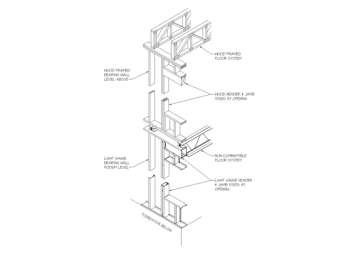
Cold-formed steel framing has a long history of being used for curtain walls and load-bearing walls for taller residential buildings up to 12-stories when non-combustible framing members are needed for the main structural system. However, for buildings up to 5 or 7 stories in height with podium levels transitioning to more residential use, a hybrid system consisting of CFS bearing walls supporting a non-combustible floor system with up to 4 to 5 stories of wood framing above can be an effective option.
For podium structures, the horizontal separation must meet the criteria outlined in the 2018 International Building Code (IBC), Section 510.2, summarized below:
- A 3-hour fire-rated horizontal assembly separates buildings
- The horizontal assembly and the building below are Type I-A construction
- Shaft, stairway, ramp, and escalator enclosures to be 2-hour rated
- The building above the horizontal assembly is permitted to have multiple Group A occupancy uses, each with an occupant load of less than 300, or Group B, M, R, or S occupancies
- An automatic sprinkler system shall protect the building below the horizontal assembly
- Maximum building height satisfies the limits in Section 504.3
As indicated in items 1 and 2, CFS bearing walls below the horizontal assembly are a viable alternative to traditional podium framing, which typically consists of steel beam and column construction or concrete transfer slabs.
The advantage of this hybrid system is that the bearing walls can stack and directly support the wood bearing wall levels above. Floor layouts can be maintained with minor adjustments for wall sizes, thus leaving the unit spaces, window locations, and utility locations largely unaltered between the podium and upper floors. A maximum of two levels of CFS bearing walls can be utilized while maintaining the height limitations outlined in IBC section 504.3 for either Type V-A or Type III-A construction.
Design Considerations
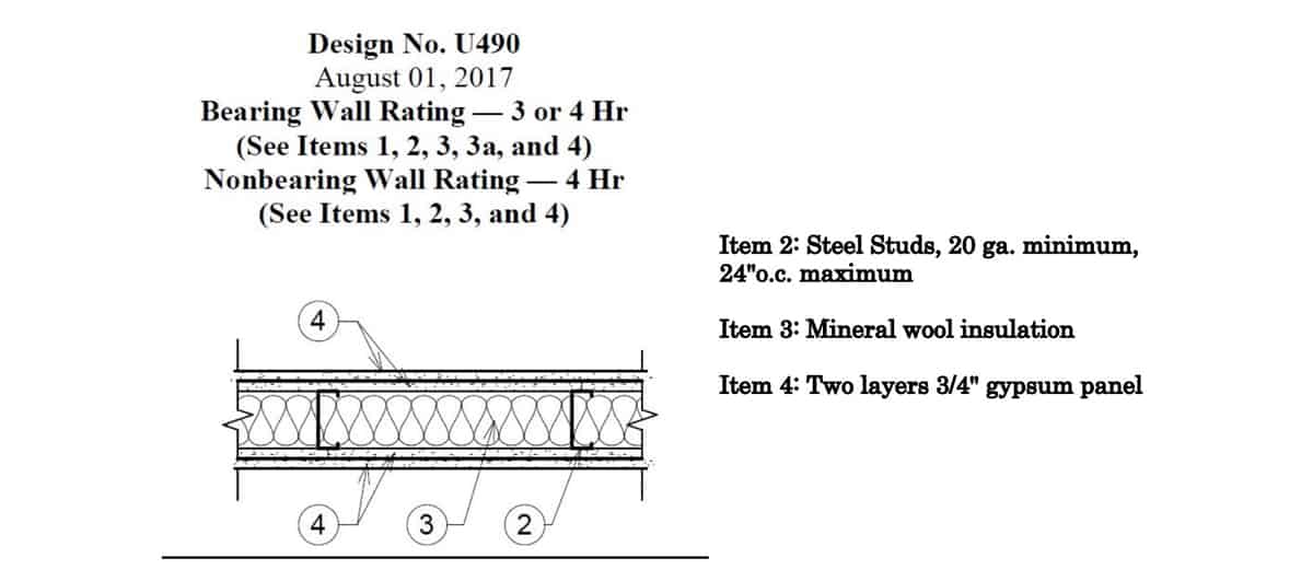
The primary impact on architectural plans is minor dimensional shifts within the units. The 3-hour fire rating required for CFS structural elements supporting podium levels results in drywall thicknesses of approximately 1.5-inches to 2-inches thick on the rated side of the wall. Additionally, most bearing walls typically provide CFS studs in sizes of 3⅝-inch, 6-inch, or 8-inch depths. These sizes are larger than the respective nominal wood stud sizes of 3½, 5½, or 7¼ inches. The combination of the 3-hour fire rating assembly and larger CFS stud sizes results in slightly smaller units at the lowest level but rarely affects the overall layout.
The mechanical systems used at the wood-framed levels can also be used at the CFS bearing wall level. Vertical risers can be continued down through the wall cavity to the foundation with minimal impact on the framing. Wall stud bridging members and shear wall locations may need to be coordinated with risers depending on the types selected by the structural engineer. Horizontal runs of electrical wiring and plumbing supply lines can fit within the web punchouts provided in standard stud sections. However, the plumbing drains must be placed in furring or wet walls whenever possible, as the required drainage slope may not align with punchout locations. Field cutting web holes in metal studs is not recommended due to more strict limitations on size and location than what is allowed for wood studs. The design standards produced by the American Iron and Steel Institute (AISI) may be referenced for further information about acceptable holes in CFS stud framing.
The lateral system used for the wood-framed and CFS levels must be compatible. At the wood-framed levels, drywall or wood structural panel sheathed shear walls are the most common method of lateral bracing utilized in stacked construction. The shear walls are located at the corridor and unit demising walls that stack from the uppermost level to the foundation. At the CFS levels, shear walls are sheathed with steel sheets or braced with light gauge X-braces. By utilizing shear walls at all levels, the shear walls can be stacked down through the full height of the building, simplifying the lateral system.
Reinforced vertical masonry cores, concrete cores, or steel moment frames may also be used for lateral bracing. These systems are best used only where needed to accommodate large open areas that do not allow the stacked shear walls to continue down through the building. When cores and moment frames are utilized, special design considerations are required to ensure the lateral force of the stacked shear walls is transferred to these elements through collectors and chord members. The connection of the diaphragm to the cores or moment frames also needs to be correctly detailed to ensure that the concentrated lateral loads are transferred to the vertical lateral elements.
Regardless of which lateral bracing system is selected, it is possible to use a two-stage analysis as outlined in ASCE 7, Minimum Design Loads and Associated Criteria for Buildings and Other Structures, Section 12.2.3.2, similar to traditional podium buildings. When designed appropriately, the lateral stiffness of the restraint system utilized for the CFS bearing walls can meet these requirements, thus significantly reducing the seismic loads on the wood shear walls.
Floor Systems
A non-combustible 3-hour fire-rated Type I-A floor system serves as the podium level and bears on CFS walls. A CFS bearing wall system allows for various floor assemblies that satisfy the 3-hour fire rating and the finish requirements for residential space. Common types include composite metal joist, precast concrete plank, and deep flute metal deck. Each has its own set of benefits and drawbacks when determining which one is best for a given project. Listing all floor systems and design considerations is beyond the scope of this article. However, general considerations include but are not limited to: compatibility with CFS bearing wall framing, fire rating of the assembly, fabrication lead time, floor profile thickness, maximum shored and un-shored spans, re-shoring requirements, soffit requirements, flexibility in supporting offset loads, flexibility with field modifications, load distribution member (LDM) requirements, and weight of the floor system. These factors and more need to be weighed by the design team to determine the best option for a specific project. It is also best to involve the general contractor, if possible, to help determine relative costs and availability of materials to meet the project schedule.
The overall weight of any floor system presented is often lower when compared to cast-in-place concrete and is similar to a steel podium structure. This is due to the significant reduction in required concrete volume compared to typical reinforced concrete slabs. The lighter system has lower foundation loads that result in smaller footings and reduce the seismic demands on the structure.
Cost Considerations
On most, if not all, projects, the primary concern for the developer and contractor is cost. The costs of any project can be affected by multiple factors, but the most significant effect often comes from material type and volume. As previously mentioned, the hybrid system is lighter than traditional podium construction methods due to light-framed wood construction at the upper floors and the potential for reduced concrete volume at the podium and foundations. In addition, the reduced seismic demand on the shear walls can result in less expensive or fewer shear walls being required for the structure.
A traditional podium level requires interior partitions for unit separation, corridors, and unit interiors when used for residential units. The CFS bearing wall system takes advantage of this fact by using these walls as the structural support for the building. Walls that would already exist and have drywall or insulation for sound and fire rating purposes can also function structurally. The increased fire rating of 3 hours can be achieved through additional layers of drywall, which do not require specialty contractors to install.
The cost of a project is directly related to the construction schedule. Cold-formed steel bearing walls and the various floor systems offer unique, time-saving options that are generally not available with typical steel and concrete framing. It is possible to stick frame the CFS bearing walls similar to the wood levels above. However, the most efficient option is to have the CFS walls panelized in a shop and delivered to the job site ready for installation. Panelizing does require lead time for fabrication but significantly reduces on-site time. Depending on site conditions and project size, entire floor levels may have the walls installed in two or three days rather than weeks. Shop fabrication also offers better quality control and tighter tolerances than field framing.
Depending on the selected podium floor system, the erection of the floor may also be faster than comparable steel or concrete framed podiums. Precast concrete plank is fabricated offsite and dropped in with minimal on-site time. Composite joists and deep flute metal deck systems can be placed quickly before pouring the concrete that sits on top. In some cases, proprietary floor systems may be assembled into larger floor panels and dropped into place with cranes. Moreover, these systems typically result in less required floor shoring compared to traditional one-way and two-way concrete slabs.
Conclusion
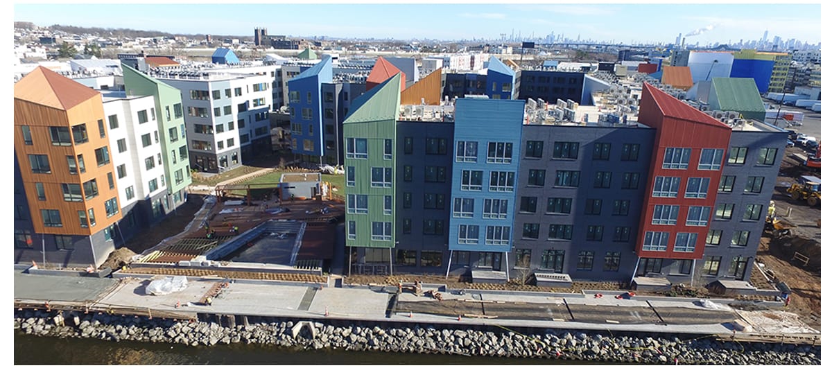
For buildings where the developer wants to maximize the use of wood framing, but the number of residential floors exceeds the limit for Type V or III-A construction, a hybrid system provides an efficient alternative to traditional podium systems. The hybrid consists of cold-formed steel bearing walls supporting a non-combustible floor system. Architects and developers succeeded with this hybrid system in buildings with stacking residential units. The benefits of CFS panelization, less shoring, and less steel framing can substantially reduce construction schedules and economic costs.■

