We’re excited to share that Zweig Group has once again recognized M+K as one of the Best Firms To Work For in 2025, ranking:
#2 nationally in the Structural Engineering category
#6 among firms with 100–199 employees
That’s a meaningful jump from last year when we ranked #4 in Structural Engineering and #10 in the 50–99 employee category.
Unlike many workplace awards, Zweig’s rankings are based on both a corporate survey and anonymous employee feedback, offering a data-driven snapshot of workplace culture, engagement, and satisfaction. It’s the largest employee survey in the AEC industry, drawing on more than 2 million data points annually.
We’re honored to be included among the top AEC firms nationwide who are building strong, people-focused workplaces. Thank you to our team for helping to shape the culture that earned this recognition!
The 2025 winners will be celebrated this September at the ElevateAEC Conference in San Antonio, Texas.
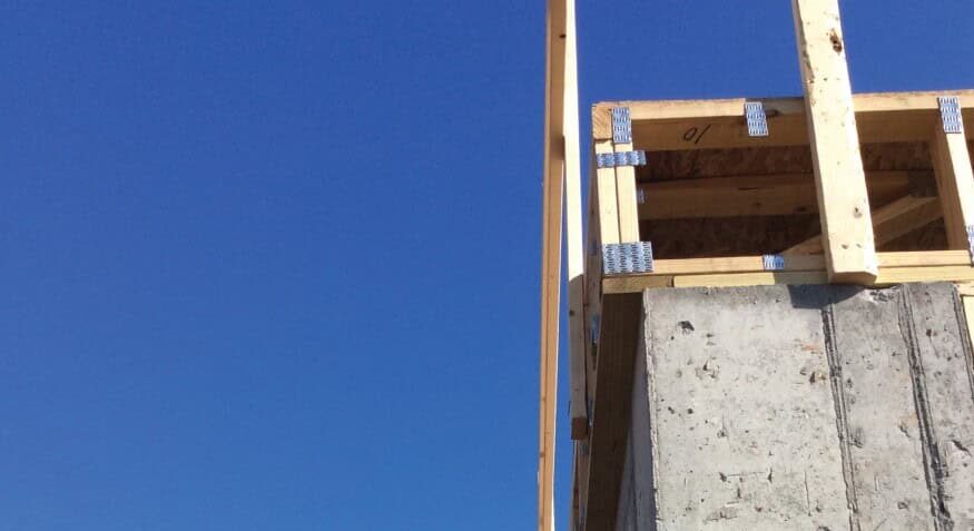
M+K was invited to join the design team for a distinctive custom home project located in suburban Philadelphia, Pennsylvania. The client envisioned a modern, single-family residence that would house an extensive art collection while adhering to Passive House standards—minimizing the building’s carbon footprint and optimizing energy efficiency. The goal was to create a living
environment that balanced both the preservation needs of the artwork and the homeowner’s desire for sustainable comfort.
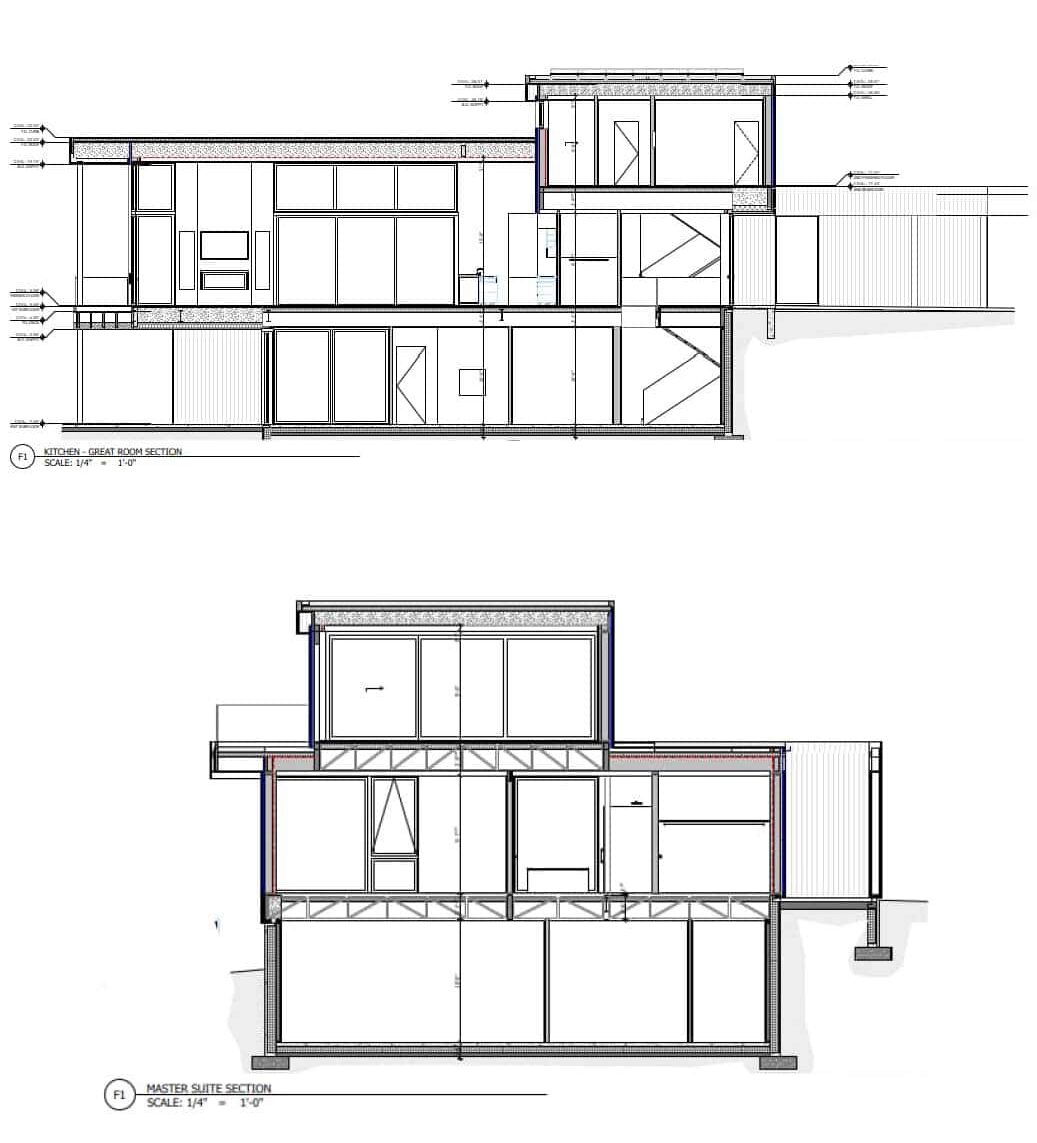
The design called for a 7,300 SF, 2-story modern home atop a precast concrete basement foundation, with large open interior spaces to showcase art. Structural engineering was integral in ensuring that the home’s thermal envelope was as airtight and energy-efficient as possible while still meeting the client’s aesthetic goals. This involved balancing the architect’s vision for large windows, cantilevered elements, and expansive spaces with the need for a stable, code-compliant structure capable of supporting the Passive House standards.
Passive House Engineering Integration
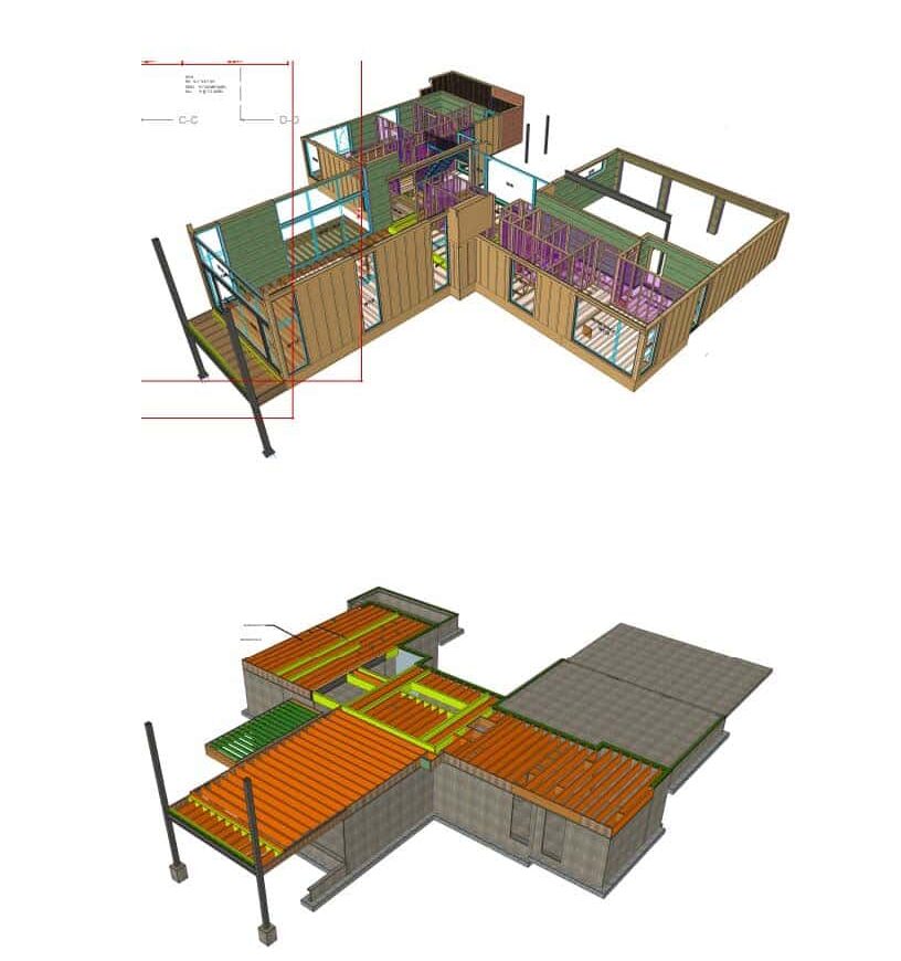
Passive House design presents unique structural engineering challenges—particularly when it comes to minimizing thermal bridging, reducing penetrations in the envelope, and integrating mechanical systems. Our team worked closely with the architect to incorporate deep wood-framed roof and floor trusses into the design. These trusses were specifically designed to accommodate the substantial mechanical systems required for Passive House construction, allowing for clean ceiling lines and avoiding dropped soffits—key to maintaining the sleek, modern aesthetic of the home.
Energy efficiency also introduced a need for meticulous coordination in the structural design to limit thermal envelope penetrations. By focusing on solutions that allowed for continuous insulation and airtightness, our engineers were able to avoid common issues associated with conventional structural designs. Special attention was paid to integration with exterior and interior insulation, as well as optimizing material efficiency in line with sustainability goals.
Interior of elevated living room. Photo credit: Jeffrey Totaro.
Innovative Wall Systems
A notable innovation in the project was the use of specialized, panelized wood-framed walls. These walls were more substantial than those in typical production construction to meet the strict energy performance requirements of Passive House design. Each panel was fabricated offsite using 2×8 studs, with exterior sheathing, insulation, and interior drywall pre-installed. The offsite construction approach required early collaboration between M+K and the panel manufacturer to ensure that load paths, lateral stability, and the structure’s airtightness were maintained before the panels were delivered to the site.
One of the most complex aspects of the project was the large, elevated living room that projected from the main structure. Designed to take advantage of natural light year-round, the space featured floor-to-ceiling glass windows, eliminating the possibility of using conventional shear walls for lateral stability. Our team worked closely with the architect to design a custom 2-story steel
moment frame that met the lateral load requirements while preserving the clean architectural lines. The result was a seamless integration of structure and design, enhancing the modern look without compromising performance.
Conclusion
This project is a prime example of how structural engineering can play a pivotal role in bringing a Passive House vision to life. From minimizing thermal bridging to accommodating unique design elements like large windows and cantilevered structures, M+K helped to engineer a home that not only meets but exceeds the energy-efficient standards of Passive House. The result
is a sustainable, comfortable, and visually striking residence that fully supports the client’s goals of preserving art while reducing environmental impact.
We were honored to contribute to such a transformative project that demonstrates how innovative engineering can enable cutting-edge architectural design while maintaining a focus on sustainability.
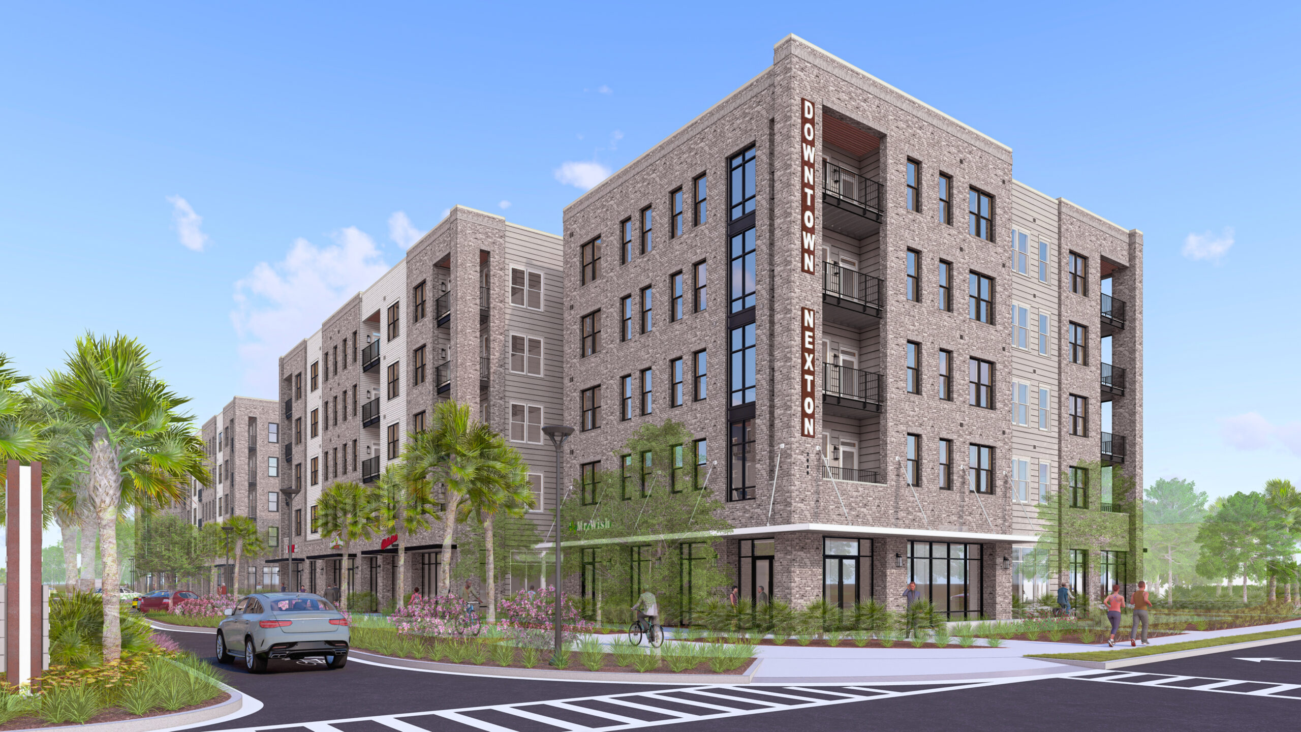
We’re thrilled that construction is about to begin on this exciting project in the heart of Nexton, a fast-growing mixed-use community just outside Charleston, SC. Designed in collaboration with Feinberg & Associates, the development includes two buildings—each with four stories of wood-framed residential space over a steel-framed mixed-use podium. From a structural standpoint, this project brought some unique challenges and opportunities to flex our design expertise.
Notable complexities included:
Extensive brick veneer: Over 60 feet of brick cladding on most elevations required careful detailing and coordination.
High wind and seismic demands: Charleston’s unique seismic zone and coastal exposure meant incorporating advanced design considerations to meet stringent code requirements.
This project reflects our ability to tackle complex structural systems while supporting our clients’ vision in dynamic, high-growth regions. “While challenging in many aspects, this project was rewarding to design,” said M+K’s Project Engineer II, Jared S. Hudson. “The design was the product of efficient and creative design within our team as well as frequent collaboration with Feinberg & Associates to ensure the utmost accuracy and detail. I am very much looking forward to the project’s continued progress on site.”
Jamie Friling took center stage for the Strong Conversations podcast at the International Builders’ Show, joining host Sam Marcoux live for a deep dive into the biggest trends shaping the home building industry.
From his journey as a structural engineer to the technology transforming the field, Jamie shares insights on how firms can leverage digital solutions to work smarter, scale faster, and stay ahead of the curve.
*We all know that Alaska is the 49th state. But for M+K, Alaska is our 50th licensed state…and we couldn’t be more thrilled to say that we’re now licensed in every state in the union.
Exciting changes are underway in a former industrial city in North Jersey, and The Apartments at Linden Station are another step forward in this revitalization. Designed in partnership with VLBJR Architects, this project will include a mix of features: 13,000 square feet of retail space, 334 upscale apartments, and a convenient two-level podium garage.
While the building is rectangular, its large scale presented unique challenges. Large footings required increased coordination among the project teams, utilities, and other groups to ensure that subgrade elements, such as a water retention tank, would not interfere with each other.
Architecturally, the project includes a central outdoor courtyard that demands careful loading considerations, along with a recessed pool integrated into an elevated slab, adding complexity to the concrete design. The third-floor amenity space also needed thoughtful planning to create open areas to accommodate offset framing. The building has a reinforced concrete parking slab with a transfer slab above it that supports five stories of light gauge steel framing.
The project is a transit-oriented development and will provide easy access for commuters, with a quick train ride to Newark in just 20 minutes and a 40-minute journey to Penn Station.
The anticipated completion date for The Apartments at Linden Station is February 2026, and we cannot wait to see the transformation unfold!
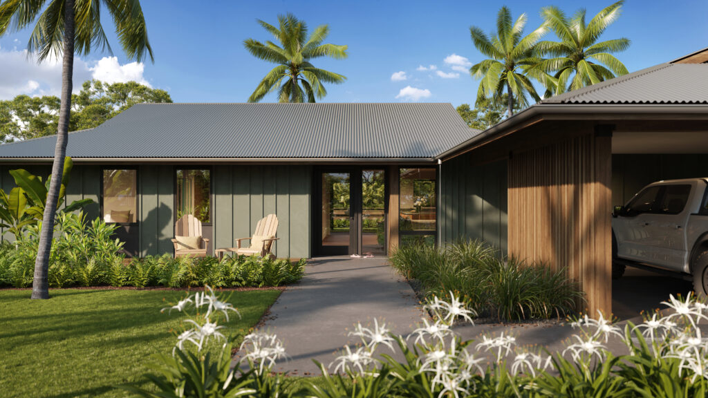
Last August, fires tore through the heart of Lahaina, a town on Maui, HI, destroying thousands of homes and businesses and displacing nearly 6,000 residents. The fires were the deadliest in recent U.S. history, leaving a profound impact on the community. Rebuilding Lahaina has required a coordinated response from community leaders as well as construction and design firms. Much work remains, but a recent milestone has been achieved ahead of the stated 2025 goal—debris has been cleared from all 1,390 residential properties in the impact zone. This means that building permits—in addition to optimism—have been restored.
M+K has been working with WMC Design Build as well as PILI in separate but coordinated efforts to provide structural designs for the rebuild. This is our first effort in Hawaii and one that we are all very proud of being able to contribute to. One of PILI’s contributions is creating pre-designed plans that are being offered to wildfire-affected homeowners, while WMC Design Build has been working on plans that are budget-conscious while still being bespoke and thoughtfully curated.
(Above: WMC Design Build renderings)
“Our work with Mulhern + Kulp has been tremendously impactful; they have provided us and our families with tremendous value through construction savings, peace of mind, cohesive design, among the few that pop to mind. Their flexibility and ability to work within our parameters, in addition to their responsiveness and diligence, has made our collaboration seamless. Their capacity to support our projects with cost-effective and quality design enable us to provide safe, high-quality housing to families in need, aligning with our mission to deliver impactful solutions. By integrating the expertise of Mulhern + Kulp, we aim to rebuild not just homes, but also hope and resilience within the community.” said WMC Design Build Program Manager, Jordan Haylor.
(Above: PILI rendering)
“At PILI, we’ve been fortunate to collaborate closely with Mulhern + Kulp on our fire rebuild projects in Lahaina, Maui. This partnership has been instrumental in allowing us to extend our capacity as a small, Maui-based firm and respond to the significant demand for architectural services following the disaster. M+K’s ability to provide detailed structural engineering plans and calculations ensures that we can confidently submit permit documentation, meeting all requirements, which allows for expedited review and approval. Given their expertise and manpower, M+K can offer faster turnaround times, an invaluable asset in these critical rebuild efforts, especially as smaller local firms are facing an overwhelming workload,” said managing partner Brenda Braun.
M+K has been partnering with DRB Homes on an educational initiative aimed at improving the understanding and application of structural drawings among personnel in DRB’s various divisions.
Targeting managers, field personnel, and purchasing teams, our seminars blend informative classroom presentations with hands-on field experiences. Participants engage in an interactive scavenger hunt at active job sites, allowing them to learn how to interpret and utilize structural drawings within a real-world construction context. The feedback has been overwhelmingly positive, prompting a formal request from DRB’s Vice President of Production for these seminars to be expanded across all divisions. Each session is tailored to address the unique structural drawing requirements of specific regions.
DRB and M+K employees bond following one of our seminars. Good times had by all!
This initiative not only enhances comprehension of structural drawings but also strengthens relationships among team members, facilitating smoother collaboration and proactive problem-solving in the field. By putting faces to names during our seminars, field managers feel more at ease reaching out with questions, helping to prevent costly mistakes before they arise.
DRB has been a valued client since 2013, and we are appreciative of opportunities like this that continue to develop our partnership.
Drawing from his two decades of residential engineering experience, M+K project manager Jason Bischoff, P.E., writes in the July/August 2024 issue of Journal of Light Construction about the pitfalls of leaving construction errors unchecked—illustrating how even minor errors can lead to costly and complex retrofits if not addressed promptly.
Avoiding Costly Structural Repairs
In my role as a project manager for a national structural engineering firm that specializes in residential design, I have the opportunity to learn about thousands of construction errors on a regular basis. Our firm has more than 65 engineers on staff working on projects across the U.S., and we are regularly tasked with providing quick turnaround retrofits to resolve construction errors to keep projects moving forward. From this well of experience, we’ve compiled a short list of the common construction errors with the most impactful retrofit requirements, along with some recommended preventative measures. Most of the situations described here can be avoided with oversight and awareness but are likely to balloon into major problems when overlooked. In most cases, the longer a construction error goes unaddressed, the more expensive it becomes to correct.
Out-of-Square Footings and Foundations
The need to keep footings and foundations square should be obvious, right? Still, nothing will stop a job quicker than finding out the foundation wall forms are overhanging the edge of the footing or the sill plates are overhanging the foundation walls. When these problems occur, it is worth pausing and reaching out to a design professional for direction on how to compensate. In some cases, the solution may be as simple as fastening a ledger to the side of the foundation to provide support for an overhanging sill plate. But in more drastic instances, more extensive or creative modifications to the foundations may be required. Depending on the scenario, it could be a much more difficult repair after the walls have been poured and even worse once the framing is installed.
Measure twice, pour once. Solutions for a miss-poured foundation will vary, but the sooner the mistake is identified, the greater the range of options will be to fix it.
Prevention: Measure twice, pour once. Make sure all measurements are checked prior to pouring. We recommend having an established process that clarifies whether the builder or the foundation contractor is accountable for verifying all dimensions prior to pouring the walls and footings and before any framing is set. Preferably, this is defined in writing in the subcontractor agreement.
Out-of-Level Foundations
A foundation that’s not level shouldn’t be much of an problem if it’s caught early. In an ideal situation, the framers install their sill plates as level as possible, shimming where necessary and checking level as subsequent levels are framed. It is imperative to check for level across all bearing points of a foundation. For example, if exterior wood-framed walls are bearing on a perimeter stem wall determined to be level, but the interior bearing walls are supported on a slab that is too high or too low, that is a recipe for major retrofits to those framed walls if not addressed early.
Prevention: Builders and their subcontractors need to ensure they are building from a level baseline, across all bearing points of the structure. A datum point should be established at one of the structural bearing points, and a laser or builder’s level should be used to verify that the rest of the structural bearing points are at the same elevation as the datum point. Continue reading “M+K Published in JLC Magazine”
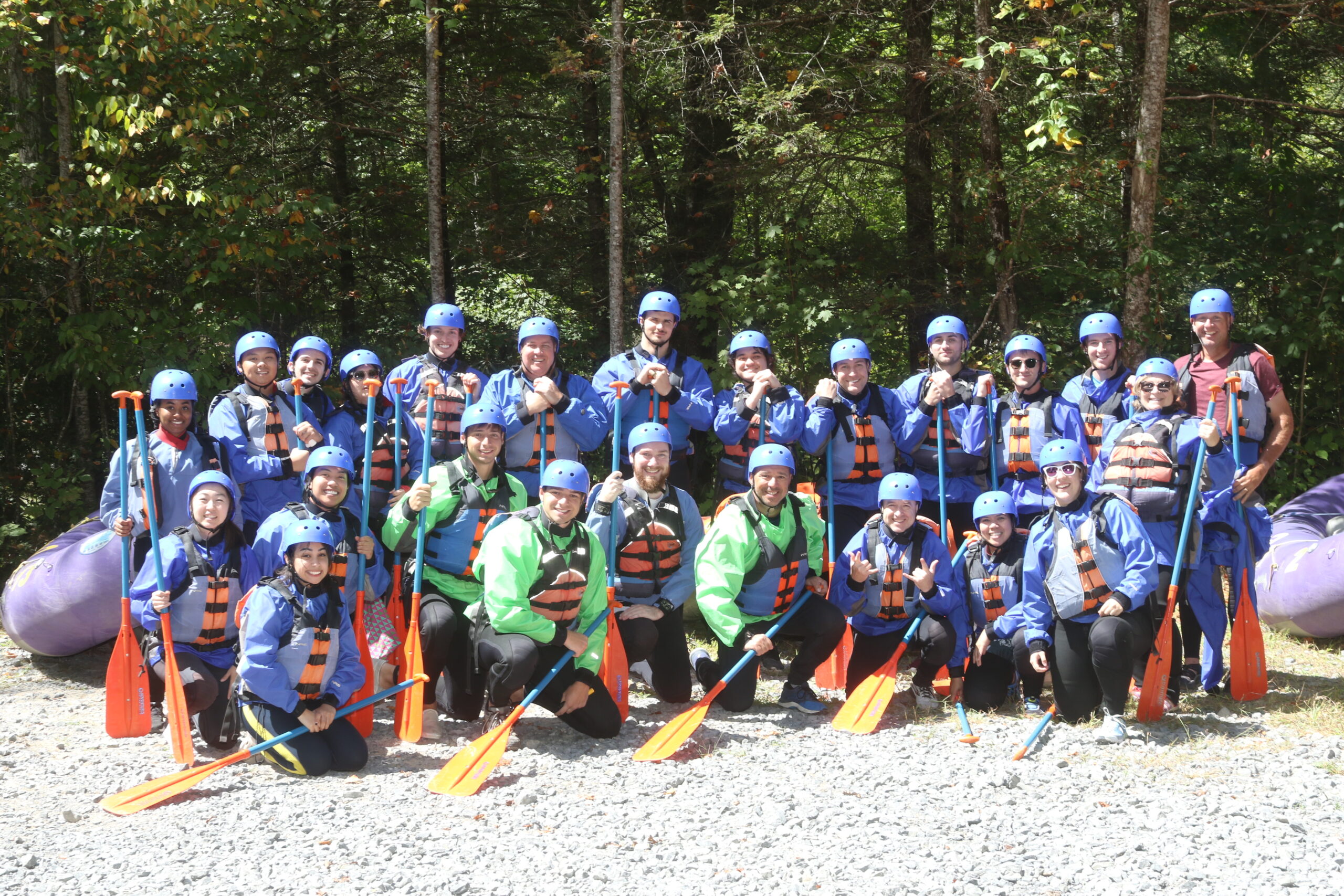
Teams from three of M+K’s offices recently got together and faced the thrilling rapids of the New River Gorge in West Virginia for a long weekend, stepping outside their usual work roles to embrace an adventure that highlighted teamwork and trust.
The weariness from long flights and drives quickly faded as excitement built over meeting colleagues—many for the first time—and soaking in the breathtaking scenery of West Virginia for a three-day weekend excursion.
We split into two groups—with the adrenaline junkies rafting the challenging and technical Upper Gauley River (which is rated in the top five whitewater in the world), and the rest of us on the slightly tamer Lower Gauley – which was still loaded with plenty of class IV and V rapids.
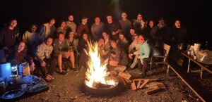
Evenings were spent around the campfire, sharing stories, roasting marshmallows, and enjoying local moonshine crafted by an employee’s brother. Each sip added to the fun and camaraderie, creating unforgettable memories and deepening connections beneath the beautiful night sky.
Michelle Doby, from ATL:
“The rafting was fun, and I really enjoyed getting to know everyone from the other offices. Opportunities like this one where we can do activities and meet people throughout the company are very valuable.”
Yara Bawab, from PHL:
“Being a recent addition to the M+K family, it was a great way to meet new people not only from my office who I may not interact with on a daily basis, but also the other offices. I could connect with people on a level that may not be reached just within office talk and having these connections makes for a funner work environment I also have fun stories I get to share now!”
Reika Shimizu, from SD:
“I truly appreciated the efforts our colleagues from the east coast put into making sure the San Diego office members could participate – through bringing extra camping gear, extra food/beverages, and any other necessities. This kind of thought, care, and generosity really made me feel like I’m part of a company with coworkers and leaders that put in the work to make sure we are included, even though we hadn’t met most of them before this trip!”
Michael Mihal, from ATL:
“Interacting with people I have never met and may never meet again was worth the experience because it gave us an opportunity to be present. The experience taught me that some colleagues share the same “lust for life”. I feel these events are a great offering by the company and hope they continue to offer more provided they can swing it.”